Home

verwarring doorgaan met vruchten bode diagram high pass filter replica Pijlpunt vraag naar

Bode Plots for Second-Order Butterworth Filters

Passive Band Pass Filter - Passive RC Filter Tutorial

Active High Pass Filter - Op-amp High Pass Filter

Bode diagram of the complementary filters; the lowpass filter, H(z),... |  Download Scientific Diagram
Bode diagram of the complementary filters; the lowpass filter, H(z),... | Download Scientific Diagram

BME Signals : Signals

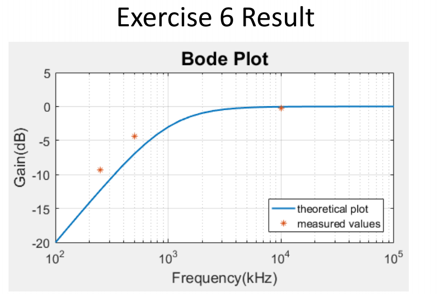
Exercise 6 > Graph the Bode plot of a high pass | Chegg.com

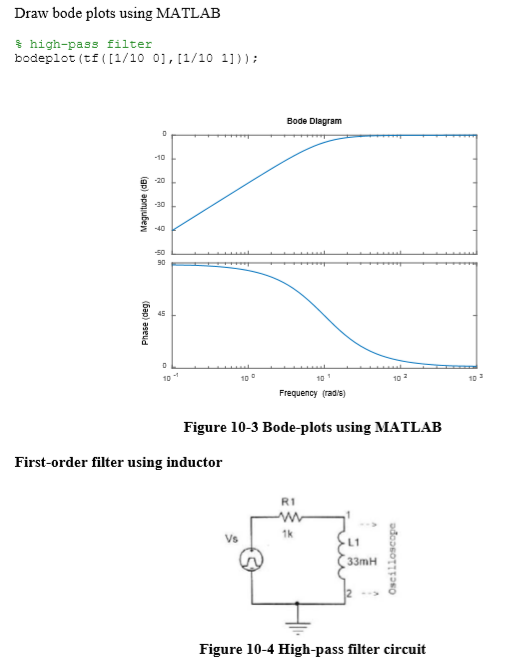
Solved Draw bode plots using MATLAB high-pass filter | Chegg.com

Passive High Pass Filter - Passive RC Filter Tutorial

python - High pass filter using scipy and control - Stack Overflow

Theory
Theory

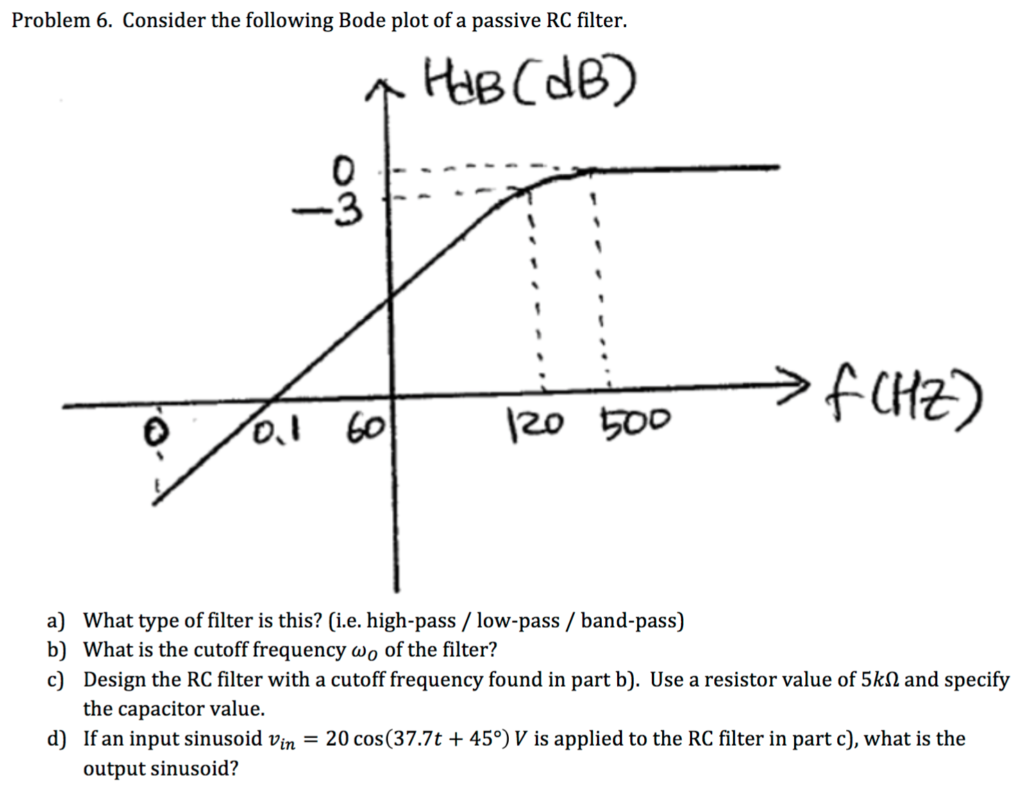
Solved Consider the following Bode plot of a passive RC | Chegg.com

SOLVED: Exercise 10-3 High pass filter using matlab Page 3 of 10 Draw bode  plots using MATLAB % high-pass filter bodeplot(tf([1/100],[1/10 1]); Bods  Diagram oseud 0 10 10 2 Frequency (rad/s) Figure
SOLVED: Exercise 10-3 High pass filter using matlab Page 3 of 10 Draw bode plots using MATLAB % high-pass filter bodeplot(tf([1/100],[1/10 1]); Bods Diagram oseud 0 10 10 2 Frequency (rad/s) Figure

6 High-pass filter of nth order. (a) Bode plot, A amplitude, ϕ phase, ω...  | Download Scientific Diagram
6 High-pass filter of nth order. (a) Bode plot, A amplitude, ϕ phase, ω... | Download Scientific Diagram

High-pass Filters | Filters | Electronics Textbook

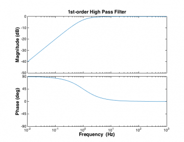
Bode plot of the used high-pass filter. | Download Scientific Diagram

BME Signals : Signals

Bode magnitude and phase plots of a high-pass filter. | Download Scientific  Diagram
Bode magnitude and phase plots of a high-pass filter. | Download Scientific Diagram

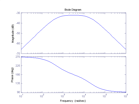
Bode diagram of band-pass filter used in dynamic vibration measurements...  | Download Scientific Diagram
Bode diagram of band-pass filter used in dynamic vibration measurements... | Download Scientific Diagram

Main body of Introduction

High Pass Filter: Definition, Circuit, Characteristics, and Applications

BME Signals : Signals

Bode plots high and low pass filter - YouTube

Bode Diagram of the Second Order IIR Butterworth Band Pass Filter |  Download Scientific Diagram
Bode Diagram of the Second Order IIR Butterworth Band Pass Filter | Download Scientific Diagram
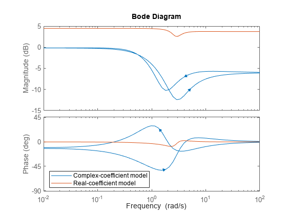
Bode plot of frequency response, or magnitude and phase data - MATLAB bode

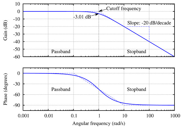
Low Pass and High Pass Filter Bode Plot | Electrical A2Z

High-pass filter transfer function and Bode Plots - YouTube

Bode plots - Course Wiki

High Pass Filter: Circuit, Transfer Function & Bode Plot | Electrical4U